
Technology Center
Recommended Products


Contact Us
Contact Person: Cindy Zhu
TEL:+86 13418453374
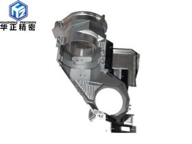
Master the complex features of machined parts
Master the complex features of machined parts
CNC machine tools get greater development every year. The movable tool lathe can mill various shapes and drill off-axis or radial holes. These operations once required a separate trip to the milling department. The machining center is equipped with an indexing head that supports 3+2 machining, and multiple sides of the part can be completed in one operation. This is good news for designers and engineers. Now not only can produce extremely complex parts, but also can produce with higher quality, lower cost and shorter lead time. But not following these rules can lead to costly rework and project delays. This article explores some key considerations that any part designer should know.
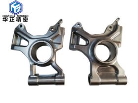
Real 5-axis machining? CNC turning on a high-speed lathe can complete many complex parts in one operation. The movable tool and Y-axis function means that the bolt can be turned, the wrench flat can be milled, and then a cross hole for the safety line can be drilled. More complex examples might include hydraulic pistons with alignment grooves on one end, fittings with wrench holes on the surface, or shafts with external keyways. In some cases, it is even possible to "turn" parts that are more orthogonal than a circle.
Considering this background of milling and powered tools, the following five elements need to be considered when designing complex parts:
1. Hole placement: The minimum size of the shaft hole and the axial hole on the CNC lathe is 0.04 inches (1 mm), and the maximum depth is 6 times the diameter. Radial holes (holes drilled from the side of the part) should be at least 0.08 inches (2 mm) in diameter. Holes through turned or milled parts are usually possible (especially on hollow or tubular parts), but depending on the part size, hole diameter, and material, the tool may not have enough range
2. Deep features: The depth of the external grooves on the turned parts must not exceed 0.95 inches (24.1 mm) deep, or less than 0.047 inches (1.2 mm). In terms of size, all other trough milling features are usually the same as drilling, but a good rule of thumb is to keep the depth less than 6 times the feature width. Also, make sure to leave at least 0.020 inches (0.5mm) of wall thickness on adjacent materials. Milling or turning of large planes and other milled surfaces depends entirely on the geometry of the part relative to the available tool size. However, no matter where it is made, deep ribs and grooves can be a challenge. It is possible to cut radiator-like features on turned or milled parts, but this depends on the actual part geometry and available tools.
3. Better threads: There is a lot of overlap in threading capabilities between turning and milling centers. Generally speaking, threads from #4-40 (M3 x 0.5) to about 1/2-20 (M10 x 1.25) can be machined, depending on the machine type and feature locations, although there are some exceptions. Here, be sure to consider the part about the correct method of thread modeling, and the relationship between this and the internal and external, milling and turning part features. You can also consider using inserts. Coil and key inserts have a longer service life than bare threads, especially in soft materials such as aluminum or plastic, and are easy to install.
4. The cost of text marking is very high: complex aerospace and medical parts usually require permanent marking of the part number and company name. The indented text looks good, but it is also the most time-consuming of all processing operations, and it is prohibitive as production increases. Generally, it is better to use electrochemical etching or laser marking of parts, but if you must engrave text, use simple, clean fonts, keep them short and beautiful. We recommend soft metal and plastic ArialRounded MT fonts at 14 points 0.3 mm deep, and hard metal ArialRounded MT fonts at 22 points 0.3 mm deep.
5. Radius: Observe the corners: A common mistake on any machined part is the sharp protrusion of the inner corner. For example, the head radius of a turning tool usually used for finishing is 0.016 inches (0.032 mm), so any design of mating parts should take this into consideration. The milling cutter is lowered to 0.040 inches (1 mm), which means that the inner corner radius of any groove will be slightly larger than half that radius. This is very sharp, but keep in mind that milling with such a small tool takes a long time and will be limited to grooves no more than 0.375 inches (9.52 mm) deep. The best way is to reduce the inner angle, or allow the largest possible inner radius in the design of the mating parts.
Prev: 6 mistakes to avoid when designing sheet metal parts
Next: ways to optimize the design of CNC machining parts
Back